NDJ Series Product Standard: Q/SGKW5
SNB Series Product Standard: Q/SGKW6
Operation Manual for NDJ Series and SNB Series Digital Viscometer
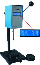
NDJ Series Viscosity Meter is a digital display viscosity meter by adopting the high subsection driven step-motor and 16 bit micro-computer controlled processor with a LCD night visual display. The said meter is stable and accurate in motion, definitude in key demonstration, programmable in design, easy for operation. The display directly demonstrates the viscosity, rotating speed, rotor number and the maximum viscosity measured for the rotor selected for the current rotating speed. The main controlling board, subsection driven board are all manufactured by adopting the Surface Mount Technology (SMT). The circuit is adopted by the micro processor that is most advance at present, with compact and reasonable structure. The RS232 is provided. The space for printing can be set up by the user. The full range and linearity at points are adjusted by PC interface . Its performance and functions have reached to the advanced level compared with the similar product in other countries.
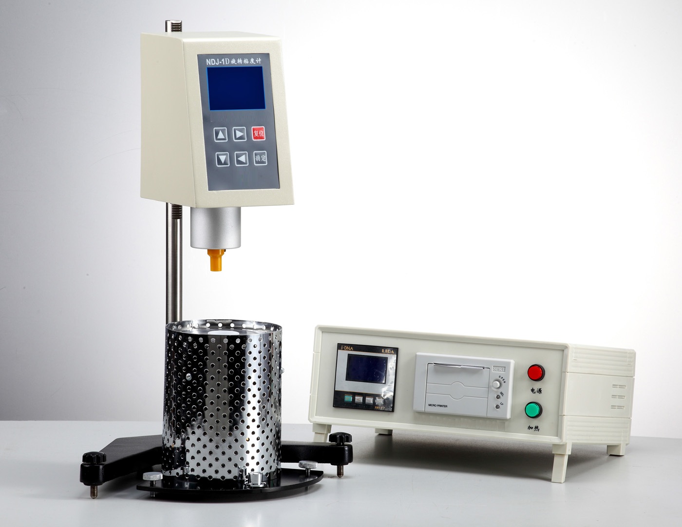
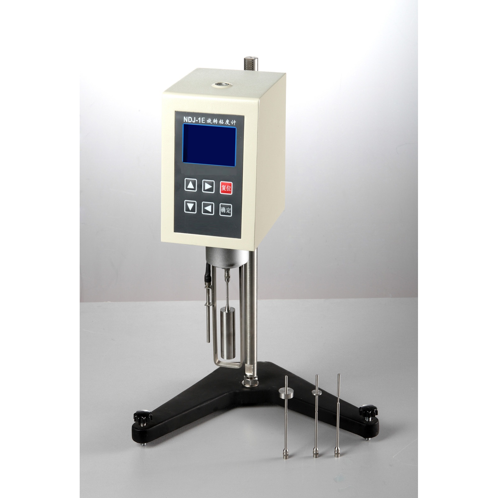
SNB Series Viscosity Meter is a updated product based on NDJ Series Viscosity Meter .In addition to the performance and features of the NDJ Series Viscosity Meter, SNB Series Viscosity Meter is measured in a wide range because its rotating speed has changed into full stepless shift gear and the data can be collected automatically through PC port. The automatic operation, saving data and data contrast and statistical analysis can be done by connecting to the computer.
NDJ Series and SNB Series Viscosity Meter are used in checking the viscous resistance and dynamical viscosity of liquid. It is widely used in measuring the viscosity of various liquid such as grease, painting, foodstuff, dope, paper making, cosmetics, chemical industry, capsule stickiness agent and medicines.
 1. Main Technical Parameters
|
Model |
NDJ-5S |
NDJ-8S
|
SNB-1 |
SNB-2 |
Measuring Range
(mPa·s) |
1—100,000 |
1—2,000,000 |
1—600,000 |
1—6,000,000 |
Rotating Speed
(RPM) |
6, 12, 30, 60 |
0.3, 0.6, 1.5,3,
6, 12, 30, 60 |
1—60
Stepless Gear |
0.1—99.9
Stepless Gear |
|
Number of Rotor |
Rotors NO.1,2,3,4 is equipped with the product
Rotor No.0 is a part optional |
|
Accuracy |
±2.0% |
|
Return Capacity |
0.5% |
|
Power |
Power adapter ( input 220+22-33V 50±1Hz, output 15V 1.2A) |
2. Structure and Principle
As shown in the picture, The pointer of the load cell driven by the high subsection driven step-motor is driving the rotor to go round and round through the hairspring and rotating axis. If the rotor is not resisted by the liquid, the pointer of the hairspring load cell is in the same position with the pointer of the load cell for the step-motor. On contrary, if the rotor is being resisted by viscous liquid, the hairspring produces the wresting square and repel and balance with the viscous resistance for reaching the balance at large. At this moment, by transmitting the output signal by the photoelectrical load cell to 16 bit micro processor for data processing, the viscous value (mPa·s) will be displayed on LCD screen with the night visual function.
 16 bit micro processor LCD display
step-motor
pointer of load cell of the step-motor
pointer of hairspring load cell
liquid to be measured
rotor
3.Apparatus to be equipped
16 bit micro processor LCD display
step-motor
pointer of load cell of the step-motor
pointer of hairspring load cell
liquid to be measured
rotor
3.Apparatus to be equipped
(1) digital viscosity meter 1 pce
(2) ascending and falling rack 1 set
(3) protective frame of rotor:1 pce
(4) power adapter: 1 pce
(5) rotors ( No.1,2,3,4 each)
(6) spanner:1 pce
(7) screw diver 1 pce
(8) socket: 1 set
Spare optional
(1) rotor No.0 ( for measuring the more less viscosity)
(2) RTD temperature probe
(3) Special software that can complete the function in collecting the data automatically
(4) specially used printer
(5) special devices for measuring a few samples
(6) remote controller
4. Installation (Please install as per the installing chart)
(1) take the seat, ascending and falling rack, main equipment, rotor support and protective rack from the box;
(2) put the ascending and failing rack into the hole of the socket and keep the opening direction of the socket and the upper rack of the ascending and failing rack facing the operator and then screw down the nut M12 with the spanner.
(3) By running the knob of the ascending and failing rack, check the agility and self-locking capacity of the collet of the ascending and failing rack. If loosing and tightening are found, you can adjust the bolt M4 on the back of the ascending and failing rack with the screw driver to make sure that it can be ascended and fallen. It will be better if it is screwed down more less tightened so as to prevent the viscosity meter from its going down after installed.
(4) Install the viscosity meter on the ascending and failing rack and make it tighten with the bolt. The bolt that is unscrewed under the apparatus and remove and place the cap in yellow properly for next use. The cap in yellow plays a role in preventing the joint screw. It should cover the cap in yellow if it is not used for a longer time or being transported.
(5) By adjusting 2 leveling feet to make sure that the bubble is in the middle position of the viscosity meter on the top.
(6) Please install it to the interface if KTD temperature probe is available. The printer is installed on the interface RS232 if any.
(7) To make sure the viscosity meter is on OFF and then turn it on.
5. Function of keys

Reset the applied program

Printing function
Selection of the motor rotating speed


Start to measure

Rotor Selection. The viscous value maximum measured under the current rotating
The 4 keys mentioned below are used in SNB Series Product ( for digital setting only)


The number goes up The number goes down


shift rightwards shift leftwards
6. Content Description on scree
Is is displayed when switching on and resetting the apparatus
SNB-1=Model of the apparatus, it will be displayed after 3 seconds
|
20.0 ℃ 60.0 RPM 45.7% 888888.8 SP 4 mPa·s |
20.0 ℃ stands for the temperature measured by KTD temperature probe at ℃
SP 4 stands for Rotor No.4, 0 stands for rotor No.0, 1 stands for rotor No.1,…… The rest can be known in such sequences
60.0 RPM stands for the current rotating speed at RPM
888888.8 mPa·s stands for the maximum viscous value measured under the current rotating speed for the selected rotor at mPa·s
45.7 % stands for the mark of percentage meter, or called wresting square. The mark of the percentage meter between 20% and 90% is regarded as normal figures. The viscosity meter will alarm if it beyond this figures. As result, the user will change the rotating speed and rotor.
7. Operating Procedures
(1) As per 4 installation, install the viscosity meter in place.
(2) Install the protective frame on the viscosity meter ( revolving rightwards for installing and leftwards for uninstalling)
(3) Revolving and installing the selected rotor to the bolt ( revolving leftwards for installing and rightwards for uninstalling)
(4) Switching on and the step motor starts
(5) Input the number of the rotor, the displayed number of the rotor on the screen will be changed once pressing the key of the rotor and it is circulated between 1→2→3→4→0→.The input will be over when the number of the selected rotor is displayed on the screen
(6) Selecting the rotating speed: the displayed speed of the rotor on the screen will be changed once pressing the key of the rotor and it is circulated within the speed limit specified between 6.0→12.0→30.0→60.0→.The selection of the rotating speed is over when the speed of the selected rotor is displayed on the screen
The selection of SNB Series Product: Once pressing the key for the speed, 60 or 60.0 will be displayed on the screen and flickering “6”.At this time, you can press the key for number going up or going down to set the tens digit of the rotating speed. And then press the key shifting rightwards to set the tens digit of the shifted number or decimal point. If the shift is needed in reverse direction, press the key shifting leftwards. In this way, you can set the value of other digit. Press the key for confirmation when the setting is over.
(7) By revolving the knob of the ascending and failing rack, the viscosity meter will go down slowly and the rotor will immerge into the liquid that will be measured until the mark of the rotor is in the same level with the liquid. And then adjust the position of the viscosity meter to the level.
(8) By pressing the key for measurement, you can measure the viscous value of the rotor under the current rotating speed and mark of the percentage meter at the same time.
(9) In the course of measurement, if you need to change the rotor, you can press the key for reset directly. At this moment, the motor stops and the viscosity meter is still powered. After the rotor is changed, you can continue to measure as per the procedures (6)and (8)above mentioned.
(10) Printing
a. Firstly, you should select the time interval for printing. After press the key for printing, S:00:05 will be displayed on the screen. The time interval for printing will be changed once you press the key for printing. 00:05→00:10→00:20→00:30→01:00→01:30→02:00→05:00→ will be displayed on the screen to and fro.
S:00:05 stands for printing every 5 seconds, 00:10 stands for printing every 10 seconds, ……05:00 stands for printing every 5 seconds. The rest result can be known by this way.
When the time interval for printing on the screen is desired, the selection of the time interval for printing is over. For SNB Series Product, you should press the key for printing again for final confirmation.
b. After connected with the printer, you should press the key for printing once again. “on” printed on the printing paper stands for the time interval desired. After pressing the key for printing, “off” printed on the printing paper stands for the end for printing
8. Sampling measurement for unknown viscosity
(1) The General Principle for Measurement: For the sample with high viscosity, you should choose the little dimensioned rotor ( No.3, No.4) and slow rotating speed. For the sample with low viscosity, you should choose the large dimensioned rotor ( No.1,No.2) and fast rotating speed. When measured ,the mark measured by the percentage meter between 20% and 90% is the normal value. The viscous value measured within this range is the correct value.
(2)You should estimate the viscous range of the sample to be measured first and then choose the little dimensioned rotor and the slow rotating speed as per the sample with high viscosity and choose the large dimensioned rotor as per the sample with low viscosity. In most cases, you should choose the rotor and then choose the approximate rotating speed. For example, when the rotor SP is No.1,the rotating speed 60RPM,the full capacity displayed on the screen is100mPa.s. And when the rotating speed is changed into 6RPM,the full capacity is 1000mPa.s。
(3) When you can not estimate the viscosity of the sample to be measured, you should decide on the rationality of the rotor and the rotating speed as per the mark of the percentage meter (wresting square).The mark of the percentage meter between 20%—90% is the normal value. If the value is not beyond this limit, the viscosity meter will alarm, reminding the user to change the rotating speed and rotor. Never forget to change the rotor as per the principle that the rotor is changed with changing the number of the rotor SP.
9. Cautions
(1) Be careful in installing and uninstalling the rotor. When installed and uninstalled, you should operate by uplifting the joint bolt slightly. Do not do it more forcibly. Do not make the rotor receiving the force horizontally to prevent the rotor from being bended.
(2) Do not put the viscosity meter that is already installed aside or lay it down;
(3)Keep the connecting side of the joint bolt with the rotor and the screw thread itself clean. Otherwise, it will effect the shacking degree of the rotor;
(4) You should hold the ascending and failing rack in your hand when it is on raise and down to prevent it from dropping due to its deadweight;
(5)After changing the rotor, you should input the new number of the rotor. The rotor that is used and changed should be cleaned first and then put on the rack of the rotor. Do not leave the rotor on the meter and clean it.
(6)When the liquid is changed, you should clean (wipe up) the rotor and the protective frame of the rotor to avoid the error caused by the interblended liquid for measurement.
(7)The viscosity meter is matched with the rotor. Do not interblend several viscosity meters with the rotors
(8)Do not dismantle and adjust the spare parts in the viscosity meter with liberty.
(9)When the viscosity meter is moved and transported, the yellow cap should be on the joint screw and the bolt should be screwed down and packed in the box.
(10)After the rotor is installed, you do not circumrotate it for a longer in case of no liquid to prevent it from being damaged.
(11)The suspended and confused liquid, high polymer and the other more condensed liquid have a lot of “ non Newton liquid”. Their viscous values are varied with the shear speed and the time. Therefore, their checking results under the different rotors and rotating speed are different. This is the normal case. It is not the error caused by the meter. Normally, you should regulate the rotor ,rotating speed and time to measure the non Newton liquid.
(12)The following points you should pay more attention for more accurate data
a. More precisely control the temperature of the liquid to be measured
b. Putting the rotor into the liquid to be measured for an enough longer time and keep the same temperature for both
c. Keep the uniformity of the liquid
d. When measured, the rotor is placed in the center of the vessel and the rotor protective frame must be installed;
e. To make sure the cleanliness and shacking degree
f. You should turn off the apparatus at time when the measurement at high speed is changed into the measurement at low speed at one or keep a less longer time at the low speed to overcome the error that may be caused by the circumvolved inertia of the liquid.
g. When measuring the low viscosity, No.1 of the rotor is chosen, and No. 4 of the rotor for the high viscosity.
h. The measure time for the viscosity measured at low speed is relatively longer.
i. The viscosity meter can be replaced by revolving the ascending and failing collet when you need to change the rotor and liquid to be measure in process of the measurement.